

Northeastern University Capstone

Northeastern Capstone Project
The SpaceX Hyperloop Pod Competition is an annual contest where university teams gather to test their functional pod prototypes for the Hyperloop system that SpaceX aims to build for high-speed transportation in the future. Northeastern University's Hyperloop team, Paradigm Hyperloop, needed a better way to develop their lateral suspension system for the SpaceX Hyperloop competition. For my capstone project, I worked with my team to design, build, and test a mathematical, dynamic, and mechanical model for a proposed 4-degree of freedom lateral suspension system for the team's pod design. The displacement of each degree of freedom in the mechanical model is measured and compared to the theoretical data using Simulink dynamic modeling. The Hyperloop team can use this model to test various spring and damper coefficients to see how a 4-degree of freedom system reacts at various oscillation frequencies and loads. My responsibility included developing the equations of motion, designing and building the physical model, as well as wiring and programming the measurement sensors and other electrical components.

4-Degree of Freedom Mathematical Model
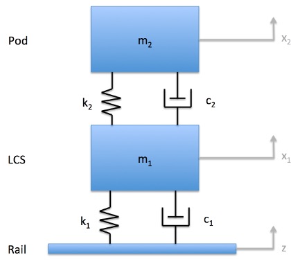
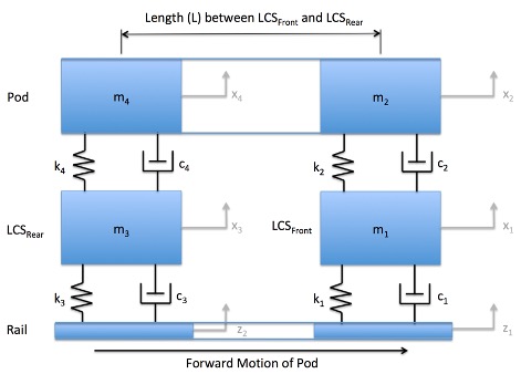
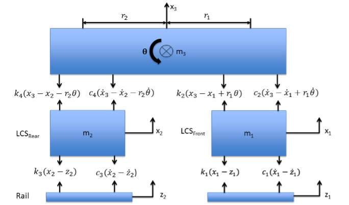
A 'half-car' mathematical model and free body diagram were created to develop the system of equations to be input into Simulink and to design the physical model. This model consisted of both a front (m1) and rear (m2) lateral suspension system under the pod (m3). The model accounted for the effect of the front and rear systems on each other, and vice versa, during oscillations. In this system, the four degrees of freedom include the displacement of both lateral control systems, the displacement of the pod about its center of mass, and the angle of the pod. With this model, I was able to develop four equations of motion for these components that were then utilized to develop the Simulink model. I developed these equations using the basic principles of forced vibration and Newton's laws of motion, where k represents spring coefficients, c represents damping coefficients, x and ẋ represents displacement and velocity of each mass, and θ represents angular velocity.
Physical Model
I was responsible for designing a physical model to simulate the lateral vibrational movement of the Hyperloop pod without having to send a model down a physical track. The forcing plates (z1 and z2) act as the driving force on the system, where they replicate potential disturbances caused by irregularities in the Hyperloop competition track. For this step, I converted rotational to linear movement using a cam with a through-hole slightly offset from its center, causing an oscillation in the system with an amplitude equal to the hole's offset distance. The cam sits on a keyed rotary shaft attached to a DC motor and rotates against a cam follower secured under z1 and z2, allowing an oscillation with a frequency dependent on the set motor speed. The cams are machined with multiple key slots around the through-hole to allow variations in the phase shift between the front and rear control systems, just as the rear of the Hyperloop pod reacts to a disturbance in the rail slightly after the front reacts to the same disturbance. z1 and z2, as well as m1 and m2 plates, are secured on linear sliding shafts with flange-mounted linear bearings to constrict movement to one axis. The pod (m3) can move along the same axis, but is also able to rotate freely in the direction shown. Thus, this system simulates the constricting, vibrating lateral movement of the Hyperloop pod's proposed front and rear lateral suspension systems (m1 and m2), as well as the slight rotation of the actual pod as the front and rear lateral control systems come into contact with the rail's irregularities.
Data Collection and Measurement Sensors
Multiple sensors were utilized in the physical model, along with an Arduino Mega as the microcontroller to measure system movement. To measure the motor frequency, a hall effect sensor was implemented in conjunction with a neodymium magnet. Given the project's price restriction, this was a way to make a cost-effective “homemade” tachometer. The magnet is placed on the motor's shaft with the hall effect sensor placed under it on a separate fixture. Each time the magnet passes the hall effect sensor, the sensor, along with its corresponding Arduino code, picks up a change in magnetic field and calculates the frequency based on the amount of time it takes for a specified amount of passes. Micro-displacement sensors are mounted above each plate (m1 and m2), as well as on each side of the pod (m3) to measure changes in displacement in real time. With each side of the pod mass' displacement considered, the angle of the pod mass as well as the displacement of the center of mass can be calculated.
